Bridge Crane Fault Repair Guide: Main Girder Deflection, Wheel Rail Gnawing and Trolley Wheel Suspension
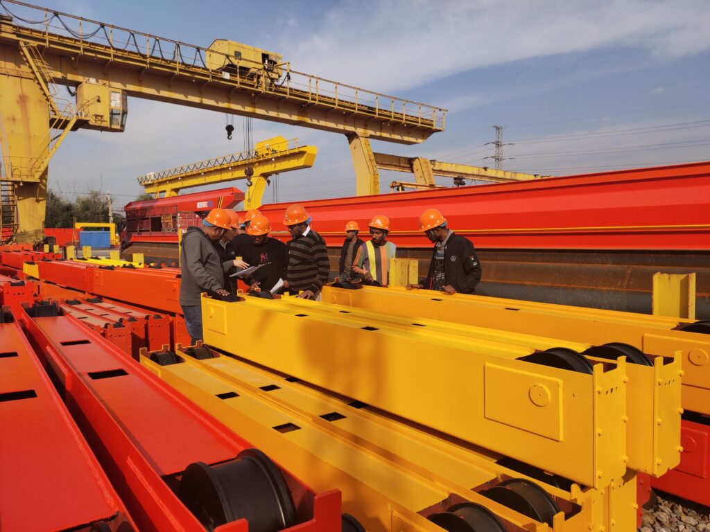
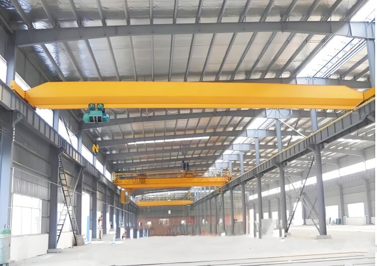
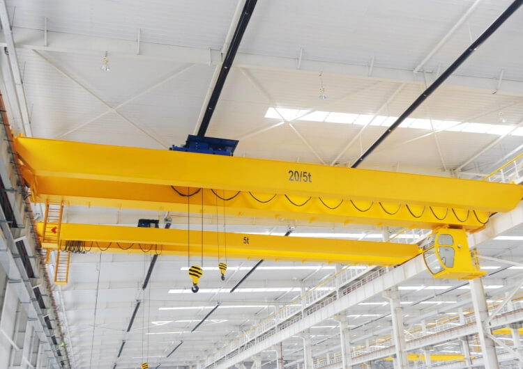
For factories and project sites in South America, Africa, the Middle East and Southeast Asia, bridge cranes are critical lifting equipment. Once the main girder is deformed or the wheels start “biting” the rail, production safety and uptime are at serious risk. For more information about different bridge crane types and configurations, you can also refer to our overhead crane overview page:
https://www.slkjcrane.com/overhead-crane/
This guide summarizes practical repair techniques for typical structural and running faults of bridge cranes, including:
-
Main girder downward deflection
-
Wheel rail gnawing (wheel flange rubbing the rail side)
-
Trolley “wheel suspension” or “three-point landing”
It is intended for maintenance engineers, service contractors and crane owners who need to extend the service life of existing bridge cranes in harsh industrial environments.
1. General Repair Requirements for Bridge Cranes
Before dismantling and repairing a bridge crane, a thorough inspection and clear repair standards are essential.
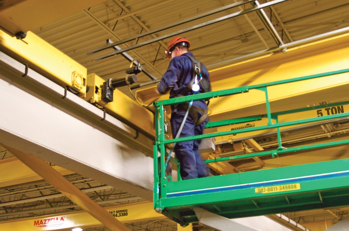
1.1 Inspection Items Before Repair
When the crane is taken out of service for repair and partially dismantled, you should carefully inspect and record:
-
Camber (upward arch) and lateral bending of the main girder
-
Actual span and any deviation from the design span
-
Wheel rail gnawing marks and rail alignment
-
Wear condition of key structural and mechanical parts
-
Any signs of torsion, local deformation or overheating in the structure
All findings should be documented to provide a baseline for repair work and later comparison.
1.2 Requirements for Replacement Parts
-
Replacement components and mechanisms must meet the original design and applicable standards
-
Surfaces must be free from burrs, dents, impact marks and heavy rust
-
All safety and signal devices and the rated capacity markings must be complete and clearly visible
-
All lubrication points must be fitted with oil plugs, oil pipes and grease nipples to ensure proper lubrication during operation
1.3 Coating and Nameplate Requirements
-
The crane’s paint color and safety markings should comply with relevant industrial standards for mining, construction and lifting machinery
-
Product nameplates and key component nameplates must be complete, firmly fixed and easy to read, for identification and traceability
These basic requirements form the foundation for safe and reliable repair work. For a more systematic overview of crane safety practices, inspections and accident prevention, you may refer to our dedicated safety guide:
https://www.slkjcrane.com/crane-safety-guide-ensuring-safe-operations-and-accident-prevention/
2. Repairing Main Girder Downward Deflection
Main girder downward deflection is a typical structural fault on older or heavily loaded bridge cranes. In severe cases, it reduces lifting height, increases local stress and may eventually lead to cracks or structural failure.
Common repair methods include:
-
Flame straightening
-
Prestress tie-rod method
-
Prestress tensioning devices
2.1 Flame Straightening Method
Flame straightening uses the principle of thermal plastic deformation. Local areas of the bottom flange and web of the main girder are heated with a gas flame to a controlled temperature and then allowed to cool naturally. When these areas cool and shrink, the girder produces a permanent upward camber, which compensates for the previous downward deflection.
Advantages:
-
Simple tools and relatively easy to perform on site
-
Heating points can be arranged flexibly to correct various complex deformation shapes
-
Can smooth an uneven deflection curve into a more uniform upward camber
-
Can also level local waves in the web plate
Limitations and Risks:
-
Residual stresses in the girder after flame straightening can be high, and new deflection may develop during later operation
-
Improper heating may change the steel’s microstructure and reduce yield strength
-
For long-term safety, it is usually recommended to weld additional structural profiles to the bottom flange after straightening to reinforce the main girder
Therefore, flame straightening is mainly suitable when the deflection is moderate and experienced technicians and proper quality control are available on site.
2.2 Prestress Tie Rod Method
In the prestress tie-rod method, brackets are welded to both ends of the bottom flange of the main girder, and several threaded tie-rods are passed through holes in the brackets.
By tightening the nuts, the tie-rods are tensioned, introducing an eccentric compressive force into the girder. This causes the main girder to camber upward and offset the existing downward deflection.
Features:
-
The amount of upward camber can be controlled relatively accurately by adjusting the tie-rod tension
-
No large-scale welding is required during adjustment, so there is less risk of new welding deformation
Limitations:
-
For girders with complex deflection shapes, the tie-rod method may not fully correct all deformation
-
The compressive stress in the bottom flange and the tensile stress in the top flange must remain within allowable limits
-
Therefore, there is an upper limit on the maximum deflection that can be corrected with this method
This method is more suitable when the main girder deflection is relatively simple and within a manageable range.
2.3 Using Prestress Tensioning Devices (Prestress Stretchers)
The principle of prestress tensioning devices is similar to the tie-rod method, but uses special steel wire ropes and tensioning devices instead of threaded rods.
The traditional “one tie-rod at a time” approach is replaced by group tensioning, which simplifies construction and improves reliability.
There are two typical types of prestress tensioning devices:
-
Single-row type: designed for tension forces up to about 75 t, commonly used for repairing downward deflection on small-tonnage bridge cranes, and for preventive strengthening on larger cranes
-
Double-row type: designed for tension forces from about 75 t to 170 t, used for repairing main girder deflection on heavy-duty bridge cranes
Main Advantages:
-
Simple construction and short repair time
In many cases, the repair work can be completed on site within 3–4 hours, minimizing crane downtime. -
Reasonable repair process with clear effect
The steel wire ropes share the load evenly, and both main girders can be stressed almost synchronously. The restored camber is easy to measure and verify, and the original structure remains largely unaffected. -
Possibility of strengthening while repairing
By adding prestress tensioning devices, the effective cross-section of the main girder can be increased, improving its strength, stiffness and load-carrying capacity. -
Trackable and adjustable repair
During later service, if prestress relaxation occurs and camber decreases, the tension force can be adjusted again to restore camber.
For cranes that have not yet developed noticeable deflection, installing prestress tensioning devices in advance helps prevent future deflection and extend service life. -
Mature technology and standardized products
Prestress tensioning devices are standardized and commercialized products. Compared with replacing main girders, investment is relatively small and benefits are realized quickly, even though the one-time cost is higher than basic flame straightening. -
High safety level
Safety devices are integrated into the design to prevent accidents caused by sudden wire rope failure.
For bridge crane users operating under high temperature, strong sunlight and heavy loads, prestress tensioning devices provide an efficient and reliable solution for repairing main girder deflection.
3. Eliminating Wheel Rail Gnawing
During crane travel, if the bridge structure deviates laterally, a horizontal side force occurs between the wheel flanges and the rail. When a wheel flange continuously rubs against the side of the rail, wheel rail gnawing occurs.
For a deeper analysis of common rail biting problems on bridge cranes and their solutions, you can also refer to:
https://www.slkjcrane.com/common-rail-biting-problems-of-bridge-cranes-and-their-solutions/
This phenomenon:
-
Increases the load on the travelling motors and transmission system
-
Causes rapid wear of wheel flanges and rail sides
-
Introduces large horizontal forces into the bridge structure and building columns, worsening their stress condition
3.1 Typical Signs of Wheel Rail Gnawing
When the following signs appear, accompanied by increased travelling resistance and frequent electrical or motor problems, wheel rail gnawing is highly likely:
-
A bright, polished strip—often with burrs—on the side of the rail
-
Bright spots and burrs on the inner side of the wheel flange
-
Bright spots on the rail head (top surface)
-
Noticeable changes in the clearance between wheel flange and rail side over a short travelling distance
-
The crane deviates or oscillates laterally, especially during starting and braking
3.2 Main Causes
Common causes of wheel rail gnawing include:
-
Incorrect wheel alignment and positioning
-
Bridge structure deformation, changing the effective wheel span and diagonal dimensions
-
Uneven wear of wheel diameters
-
Looseness in the travel drive mechanisms
-
Improper adjustment of brakes (one side braking harder or earlier)
-
Poor rail installation accuracy, including span, straightness and level errors
3.3 Adjustment Methods
(1) Correcting Horizontal Wheel Skew
-
Adjust the thickness of the vertical shims on the angle-type bearing housings to correct horizontal skew
-
During adjustment, pry off the vertical key plates, insert the shims according to the measured values, then weld the key plates back after re-measurement
-
Typical shim thickness is around 2.5 mm, but should be determined by actual measurements
(2) Correcting Vertical Wheel Skew
Adjust the thickness of shims under the horizontal keys of the bearing housings to change the vertical angle between wheel and rail
(3) Adjusting Wheel Position
-
Remove the entire wheel set
-
Cut off the locating keys of the four bearing housings
-
Re-align and re-position the wheel set according to design dimensions
-
After accurate measurement, weld the locating keys again
(4) Adjusting Wheel Span
-
A relatively simple method is to adjust the sleeves (clamping parts) on the angle-type bearing housings, thus fine-tuning the distance between wheels to meet design span requirements
(5) Adjusting Diagonal Dimensions
-
Adjusting the diagonals essentially involves a combined adjustment of wheel positions and wheel span
-
The goal is to ensure that both wheel span and diagonal dimensions meet specification, so that the crane travels straight on both sides with minimal lateral forces
Proper elimination of wheel rail gnawing not only reduces wear and power consumption, but also improves the safety margin of the bridge crane and its supporting structure.
4. Repairing Trolley Wheel Suspension (“Three-Point Landing”)
On some bridge cranes, when the trolley runs under no load, only three wheels touch the rail while another wheel has a noticeable gap to the rail. This is called wheel suspension or three-point landing.
If the suspended wheel is a driving wheel, trolley travel under light load may cause vibrations in the bridge, leading to unstable movement.
Allowable Tolerances:
-
Both driving wheels must be in reliable contact with the rail
-
For idle wheels, a small gap of less than 1 mm is acceptable, and the total length of non-contact should not exceed about 2 m
Main causes of wheel suspension include:
-
Deformation or twisting of the trolley frame
-
Bending or misalignment of trolley rails
-
Uneven wear of trolley wheel diameters, causing unbalanced wheel loads
4.1 Simple Repair by Shimming
For minor deformation and small suspension values, adding shims is a simple and effective method:
-
On a straight and level trolley rail section, measure the gap between the suspended wheel and the rail
-
Loosen the bolts fixing the bearing housing of that wheel
-
Insert shims under the horizontal key of the bearing housing with thickness equal to the measured gap
-
Tighten the bolts and re-check wheel contact with the rail
4.2 Overall Re-alignment and Adjustment
If the trolley frame is seriously twisted or the trolley rails are obviously uneven, local shimming alone is not sufficient. In such cases, a more thorough approach is required:
-
Re-align or renew the trolley rails
-
Straighten or rebuild the trolley frame
-
After structural correction, fine-adjust the height of each wheel with shims to ensure proper contact and load distribution
5. Repair or Replace? How We Support Your Bridge Cranes
When main girders are deflected and wheels are gnawing the rails, some users immediately consider replacing the entire crane. In many cases, however, professional structural repair can safely extend the life of the crane with much lower investment.
As a bridge crane manufacturer and solution provider serving South America, Africa, the Middle East and Southeast Asia, we can support you in several ways:
-
Structural safety and service life assessment of in-service bridge cranes
-
Design and supply of new main girders with optimized camber and stiffness
-
Consulting on flame straightening, prestress repair methods and structural strengthening
-
Replacement schemes for wheel sets, rails and key wear parts
-
Customized new bridge cranes to replace severely damaged or outdated units
If your current bridge cranes are suffering from main girder deflection, wheel rail gnawing or trolley wheel suspension, you are welcome to contact our engineering team for a professional technical evaluation and a tailored repair or replacement solution.
If, in daily operation, you also face problems such as excessive crane noise or complaints about environmental noise, you can refer to our special article “How to Reduce Overhead Crane Noise” for further optimization of your crane working environment and operator comfort:
https://www.slkjcrane.com/how-to-reduce-overhead-crane-noise/
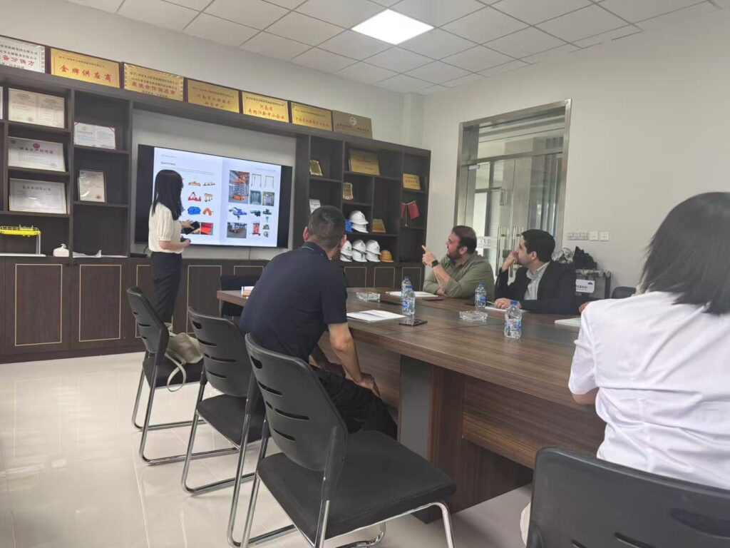
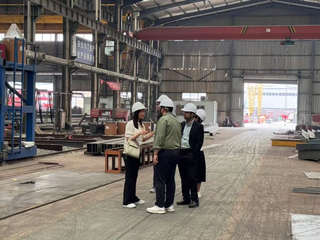
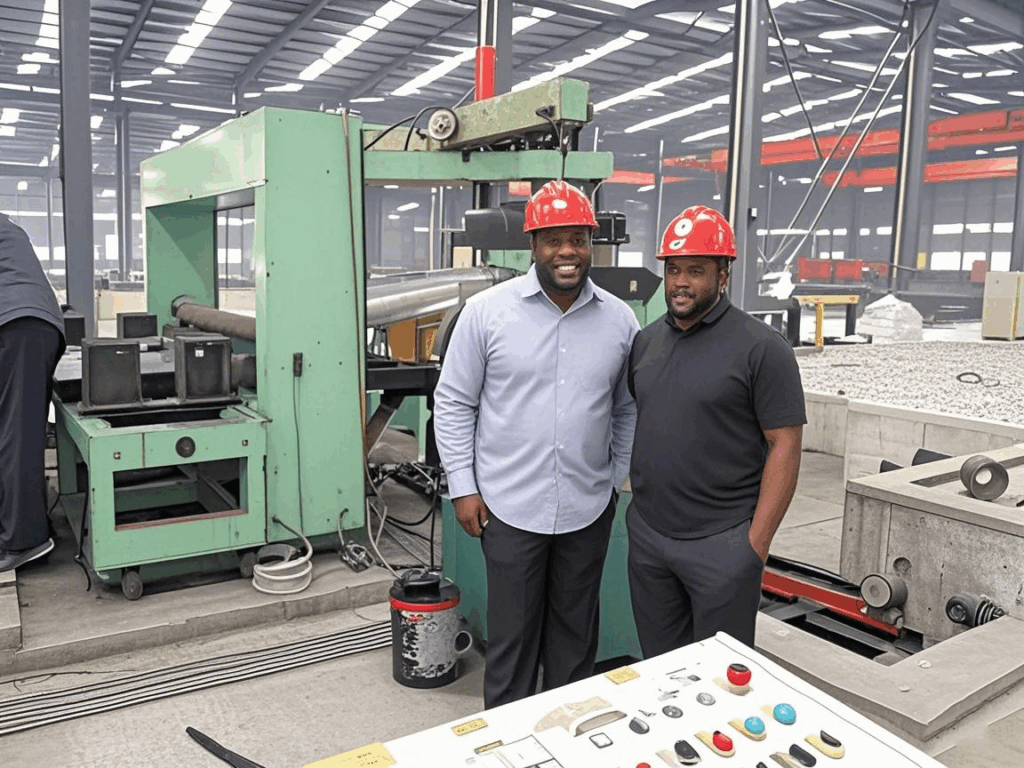
Customer case

Expert in Overhead Crane/Gantry Crane/Jib Crane/Crane Parts Solutions
Eileen Hu
With 20+ years of experience in the Crane Overseas Export Industry, helped 10,000+ customers with their pre-sales questions and concerns, if you have any related needs, please feel free to contact me!

Overhead Crane Safety Devices
Overhead Crane Safety Devices: 7 Essential Protection Systems for Overhead and Gantry Cranes Introduction Overhead cranes and gantry
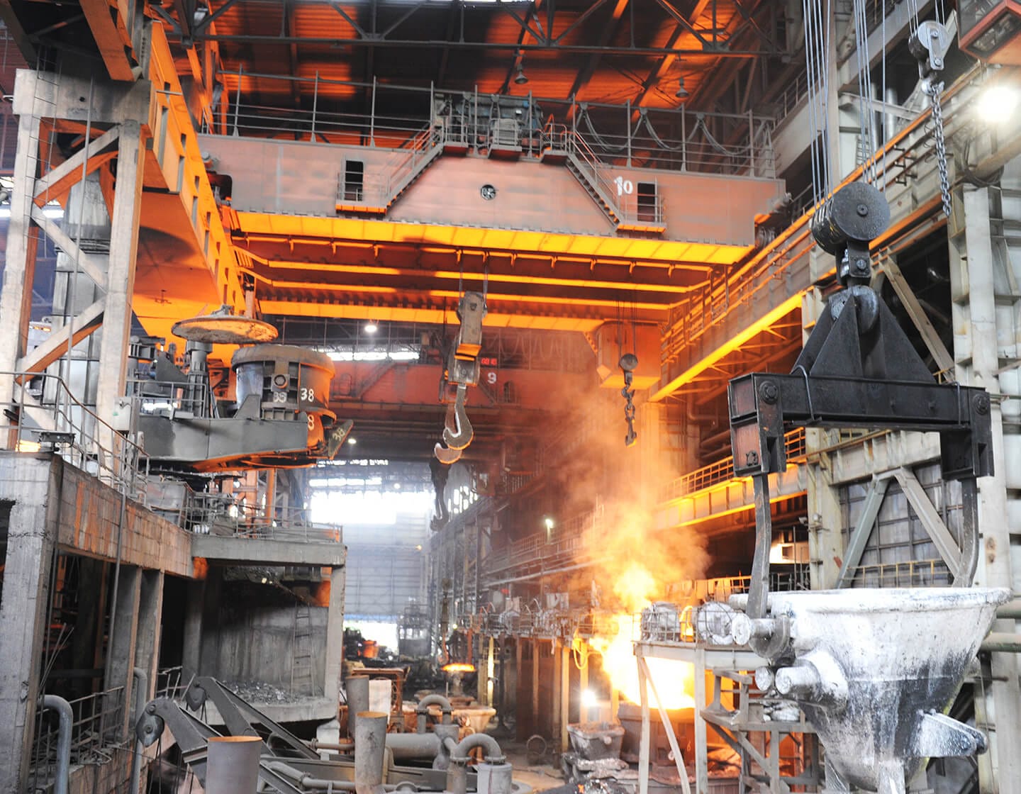
Cranes as the Backbone of Modern Steel Plants
Cranes as the Backbone of Modern Steel Plants How the Right Steel Plant Crane Solutions Drive Efficiency, Safety,
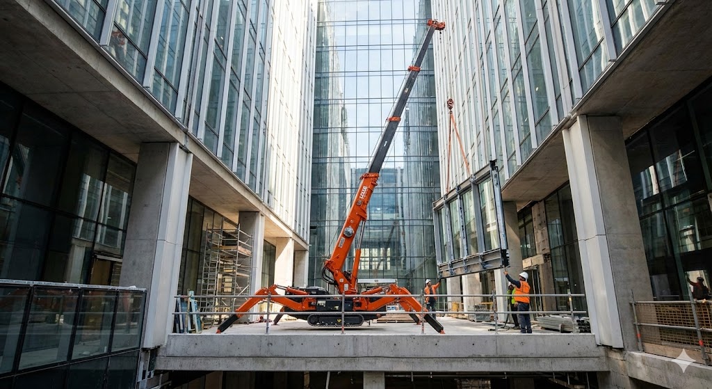
Where Spider Cranes Really Shine: 7 Typical Applications & Real Project Scenarios
Where Spider Cranes Really Shine: 7 Typical Applications & Real Project Scenarios When people ask me about spider
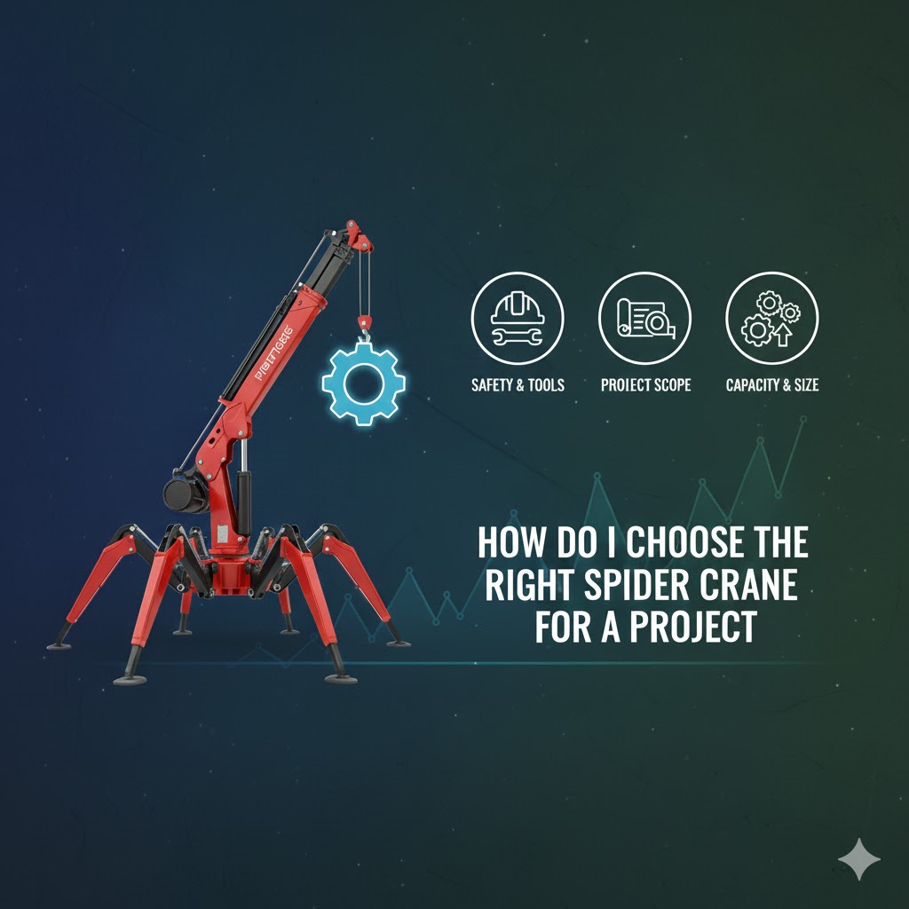
How To Choose The Right Spider Crane
How To Choose The Right Spider Crane (Mini Crawler Crane) for a Project – My Practical Experience When
Contact Us Now
Have questions about our cranes or need help?
Reach out to our friendly team for expert support and guidance.
We are here to help you power your journey towards a greener future !
Address: Crane Industry Park, Xinxiang City Henan Provice
Hot Sales
Single girder overhead cranes
Double girder overhead cranes
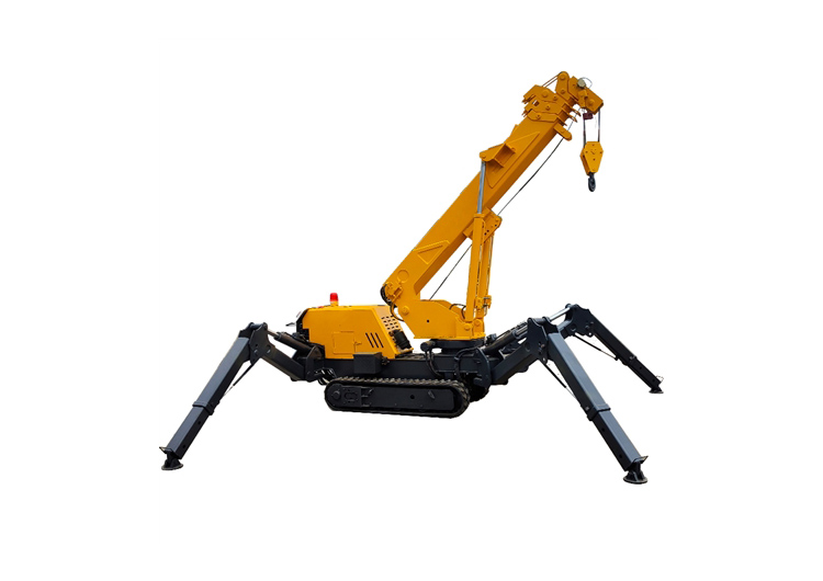
Spider cranes